如果安全互鎖裝置本體或促動器的安裝位置調整不當,或者因使用過程中的振動與衝擊導致位置偏移,可能會導致無法正確偵測門的開關狀態,甚至造成安全互鎖裝置的損壞,影響設備的正常運作。因此,針對安全互鎖裝置的安裝,規定了以下要求。
安全互鎖裝置本體的安裝要求
應依照製造商的指示正確安裝,並確保安裝後的位置不會發生變化,需滿足以下條件:
・ 安裝方式需可靠,且拆卸時需使用工具(註 4)。
註 4)硬幣或指甲銼等臨時性工具不被視為正式工具。
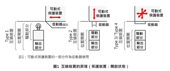
・ 對於 Type 1 安全互鎖裝置,調整後需具備永久固定的方法(例如使用插銷、定位銷)。
・ 需具備可接近安全互鎖裝置的方式,以便維護與動作確認,但必須考慮防止其被預期內的方式無效化。
・ 需防止因自然因素導致的鬆動。
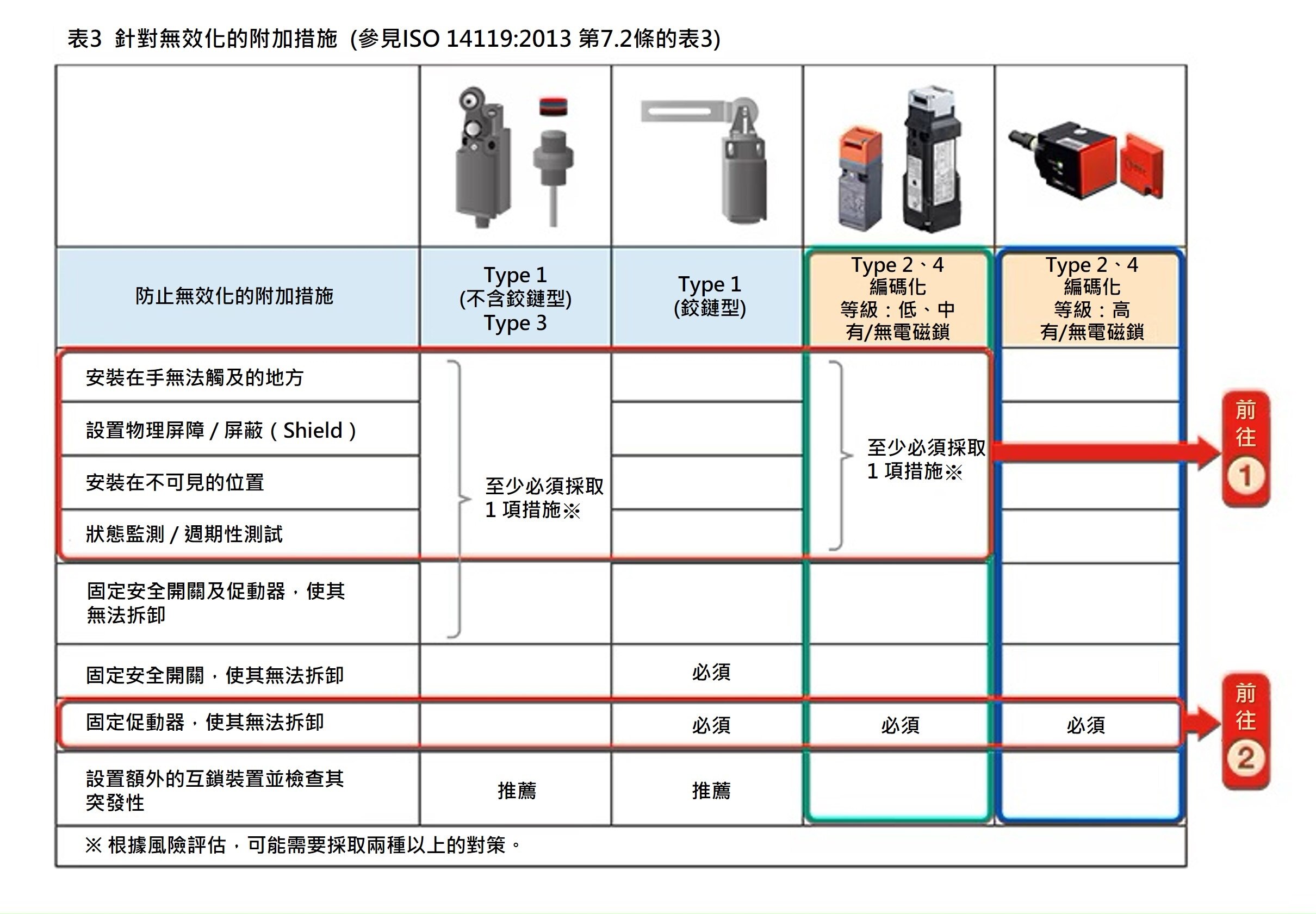
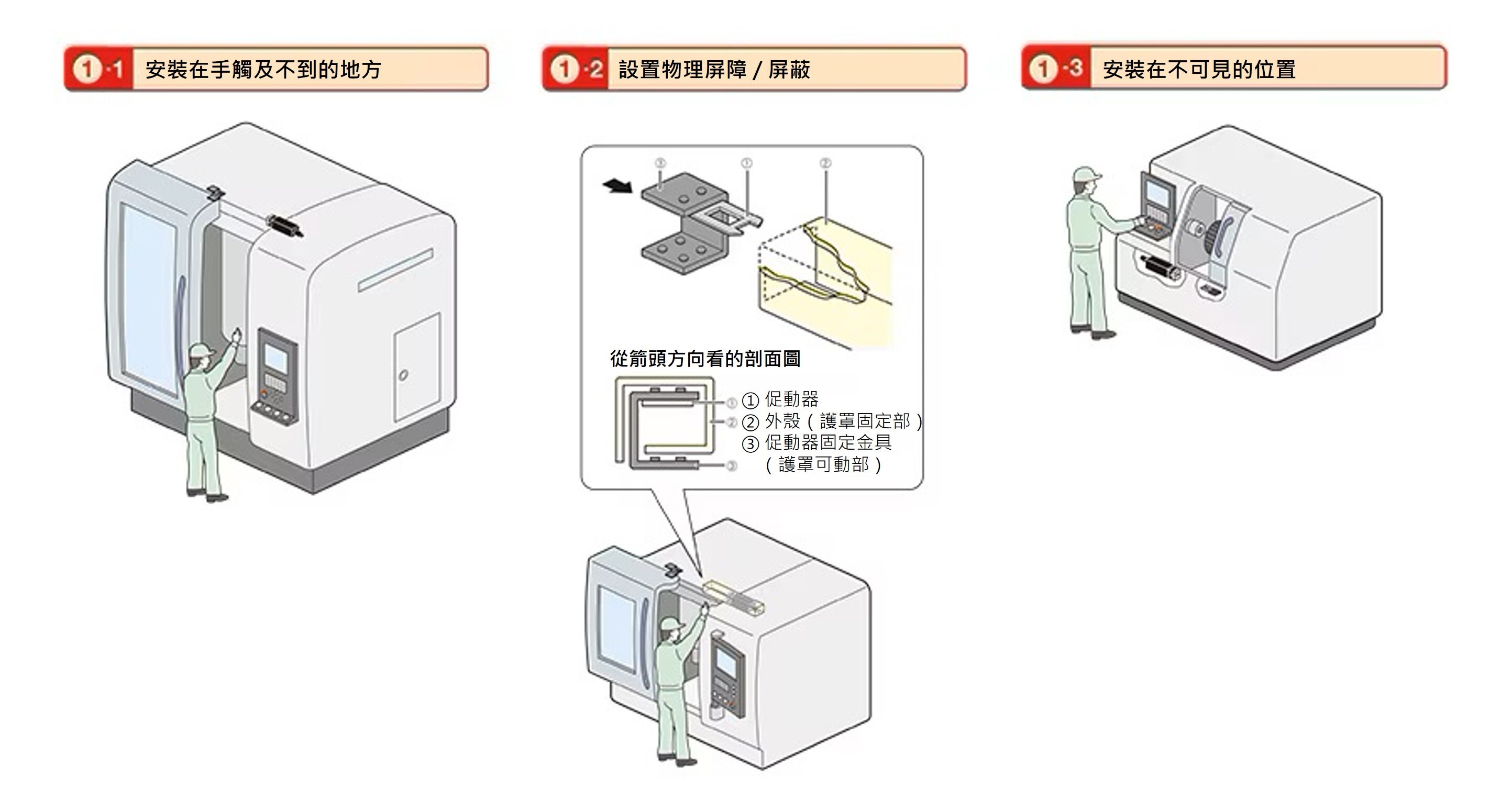
・ 需防止裝置被可預見的方法無效化。
・ 應避免因可預見的外部因素造成損壞,如有必要應提供防護措施。
・ 促動器與安全互鎖裝置本體的相對位置應遵循製造商的指示。
・ 不得將安全互鎖裝置用作機械止擋(除非製造商允許)。
・ 不得因安裝錯誤導致防護裝置產生縫隙,使人體部分可能從間隙伸入內部,造成事故風險。
・ 裝置應牢固安裝,以確保正確運作。
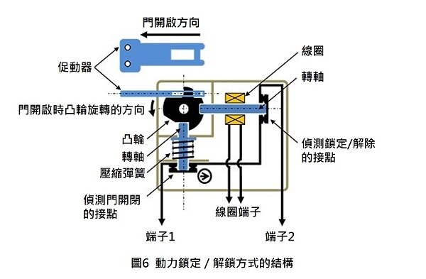
・ 對於 Type 2 安全互鎖裝置,為防止機械部件因灰塵污染或劣化,應在促動器插入口加裝防塵蓋,或確保其安裝方向避免灰塵進入。。
促動器安裝要求(5.2 項)
為了在預期壽命內最大程度減少鬆動或安裝位置變化的可能性,需滿足以下條件:
・ 安裝方式需可靠,且拆卸時需使用工具(註 4)。
註 4)硬幣或指甲銼等臨時性工具不被視為正式工具。
・ 需防止自然鬆動。
・ 應避免因可預見的外部因素造成損壞,如有必要應提供防護措施。
・ 不得將促動器用作機械止擋(除非製造商允許)。
・ 應牢固安裝,以確保裝置能夠維持正確運作。
當系統的綜合性停止性能 ≧ 人員接近時間,因此需要使用具鎖定功能的安全互鎖防護裝置時,危險機械功能的啟動必須符合特定條件。這些條件包括:防護門必須關閉,且處於鎖定狀態。
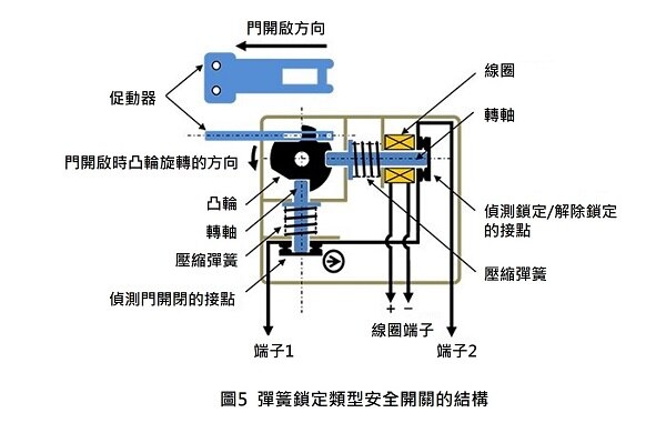
例如,如【圖 5】 所示,可透過將防護門開/關偵測接點與鎖定/解鎖偵測接點串聯來滿足此條件。
另一種方法是,採用 當防護門關閉並鎖定時才會導通的 NC(常閉)接點,透過安全開關本體的設計來實現該條件。
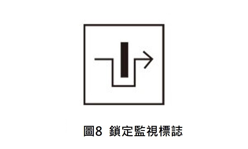
這類僅在防護門關閉且鎖定時才能啟動危險機械功能的回路,會顯示如【圖 8】所示的鎖定監視標誌。
根據 ISO 12100 的規定,當風險評估的結果導致採取安全對策時,確認這些對策是否會產生新的危險源是非常重要的。這項原則同樣適用於 具鎖定功能的安全互鎖防護裝置。
當綜合性停止性能 ≧ 人員接近時間 時,會安裝具鎖定功能的安全互鎖防護裝置,以確保在危險機械功能完全停止之前,人員無法靠近。但同時,必須確認該裝置是否會導致新的危險源。
機械的大小與類型各不相同,其中特別需要注意的是人員可能完全進入鎖定式防護裝置內的大型機械。對於這類機械,當防護門上鎖時,必須確認是否會導致操作人員或維修人員被困在機械內部,進而產生新的危險。
如果存在因被困而導致的潛在危險,則必須配備在緊急情況下供外部人員在緊急狀況下解除鎖定的「緊急解鎖功能」和供內部人員在必要時自行解除鎖定,以防被困的「內部逃生解鎖功能【圖 9】」。此外,如果防護裝置發生故障時,允許從外部解除鎖定,以便進行檢修或救援則可能需要「輔助解鎖功能【圖 10】」。